Geology Reference
In-Depth Information
1.0
0.8
0.6
0.4
(a)
H plane (TE)
E plane (TM)
(b)
K = 1
K = 4
Air
Ground
Null
Null
H plane (TE)
E plane (TM)
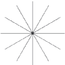
Figure 10.11
Polar radiation plots showing radiation power in the H- and
E-planes for a dipole antenna. (a) Radiation patterns in free space. (b)
Radiation patterns with the antenna resting on ground with permittivity
K
=
4
. In each case the plots are normalised to the power radiated vertically
downwards from the antenna mid-point.
If a reflector dips at the same angle as one of the nulls, little or no energy
will be reflected. Awareness of this phenomenon is important, especially if
the reflector orientation is poorly known (in which case it is advisable to
collect bipolar data).
Antenna orientation is also important in relation to linear targets such as
buried pipes. Dipole antennas are most sensitive to such objects when they
lie parallel to the dipole long axis, as is the case with Target A in Figure
10.12. In contrast, Target B will be difficult to detect unless the antennas
are turned through 90
◦
(which could involve running a second survey along
orthogonal survey lines). Some manufacturers produce GPR systems with
in-built cross-polarised dipole antennas to achieve maximum detectability