Geology Reference
In-Depth Information
Z
Z
Z
Y
Y
Y
X
X
X
Figure 10.9
Schematic drawings showing, from left to right, dipole, bow-tie
and horn antennas.
physical dimensions of a bow-tie or dipole antenna should be similar to the
wavelength of the signal in the ground.
GPR principles are most simply discussed in terms of dipole antennas,
which in free space radiate with cylindrical symmetry about, and zero inten-
sity along, the dipole axis (Figure 10.10). This simple pattern is drastically
modified by the ground. As shown in Figure 10.11, the angular position of
a reflection point relative to the antenna strongly affects the strength of the
received signal. The peaks in the H-plane pattern and the nulls in the E-
plane pattern are governed by a critical angle that depends on the dielectric
properties of the subsurface:
θ
c
=
sin
−
1
1
√
ε
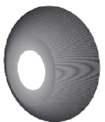
Figure 10.10
Idealised total free-space radiation pattern for the dipole
antenna shown in Figure 10.9. The vertical axis of the dipole (x-z) is called
the E-plane, or TM, and is orthogonal to the H-plane (TE). For an ideal
dipole, no fields are produced off the ends of the antenna.