Geology Reference
In-Depth Information
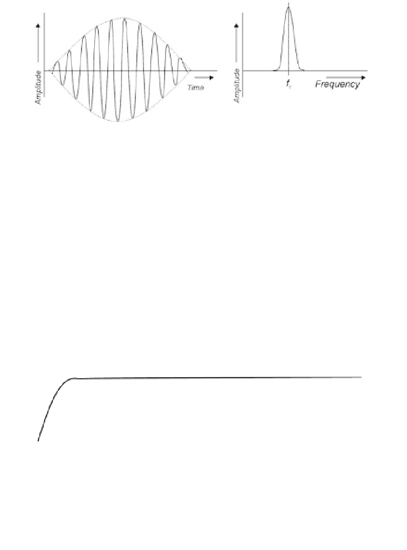
Figure 10.7
Narrow bandwidth signal derived from a long oscillatory pulse
(modulated sine wave) with a single dominant frequency,
f
c
. A series of these
waves will be transmitted in a stepped-frequency radar system.
10.1.8 Antennas
A multitude of antenna types are available, each designed to maximise
the SNR with a specific function and scale of search in mind. Some of the
commonest are shown schematically in Figure 10.9. All obey the general rule
that the lower the frequency, the larger the antenna. A change in frequency
thus normally implies a new antenna, but stepped-frequency systems avoid
this by using more complicated designs such as the log-spiral.
Dipole and bow-tie antennas are operated close to the ground to maximise
coupling, and in practice should not be more than 0.1-0.25 times the radar
wavelength above it. Horn antennas, used for applications requiring higher
frequencies, more directivity and limited depths of investigation, can be
raised above ground by two or three times the wavelength or even more. The
Figure 10.8
Schematic view of 'continuous' spectral output (dark line) for
a stepped-frequency radar system, compared with the spectral bandwidths
for impulse ground penetrating radar (GPR). The latter requires multiple
antennas to provide equivalent frequency coverage.