Geology Reference
In-Depth Information
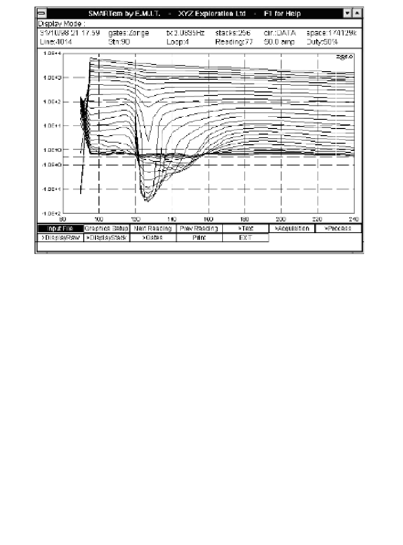
Figure 8.15
Transient electromagnetic (TEM) system profile display. The
image shows a screen dump from a SMARTem survey of a
∼
200-m profile
with a single dominant anomaly at intermediate delay times. Each curve
corresponds to a single delay time (gate). Horizontal axis is time and vertical
axis is signal strength.
dominated by eddy-currents in large-volume, relatively poor conductors.
These die away quite rapidly, and the later parts of the decay curves are
controlled by currents circulating in any good conductors present.
8.4.2 TEM depth-sounding
Transient electromagnetic methods were originally developed to overcome
some of the disadvantages of CWEM methods in mineral exploration but
are now also being widely used for depth-sounding. In homogeneous
or horizontally layered ground, the termination of current flow in the
transmitter loop induces a similar current loop or ring in the adjacent
ground. This current then decays, inducing a further current ring with a
slightly greater radius at a slightly greater depth. The induced current thus
progresses through the subsurface as an expanding 'smoke ring' (Figure
8.16), and the associated magnetic fields at progressively later times are de-
termined by current flow (and hence by resistivity) at progressively greater