Graphics Programs Reference
In-Depth Information
the fi rst feature you place in a part. It's generally made up of a 2D sketch on a
face or plane that you convert into a 3D shape. Examples of sketched feature
tools include Extrude, Revolve, and Rib.
Placed features are placed onto other features. Examples of placed feature
tools include Fillet
,
Chamfer, and Face Draft. Features that are placed or that
use the faces of other features as a foundation are said to be
children
of the fea-
tures they're built on, which are called
parent
features.
Your fi rst component (and pretty much any part) will start by using a sketch
to defi ne its basic shape. This sketch is different than the type of sketch you may
be used to creating in a 2D CAD package. The lines, arcs, and circles that make
up these sketches can be modifi ed by changing a dimension value. They can also
be related to one another to limit their size or location.
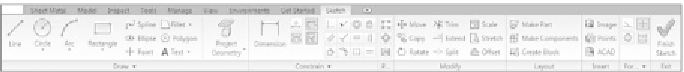
By default, when you create a new Part fi le, Inventor assumes that you want to
create a sketch. Figure 2.1 shows the Sketch toolbar as it appears when you start
a new part. In this case, it's a sheet metal part.
FIGURE 2.1
Sketch tools displayed in the Ribbon
Most of the tools in the various panels of the Ribbon will be familiar. As you
build the various components of your product, you'll use a lot of these tools.
Because Inventor has a very consistent workfl ow from tool to tool, you should
easily be able to incorporate any of the tools you don't use into future work.
Let's dive right in and start using these tools. I think you'll fi nd that it's a simple
process, so relax and get ready to enjoy using Inventor.
In this exercise, you'll create a sketch that defi nes the basic shape of the hous-
ing for a fan. When you're creating a sketch for a feature, it's best to try to defi ne
as much of the feature or component in one simple sketch as possible. Follow
these steps:
1.
Close any fi les you have open in Inventor.
2.
Make sure NER Inventor 2010 is the active project fi le.
3.
Select the New File icon under the large I icon of the Application
menu at upper left in the Inventor interface.
4.
Select the English tab in the New File dialog.
5.
Click the
Sheet Metal (in).ipt
template and click the OK button,
or double-click the icon of the template fi le to create a new sheet
metal part.


Search WWH ::

Custom Search