Graphics Programs Reference
In-Depth Information
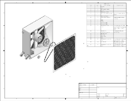
FIGURE 9.21
The parts list in the drawing
Balloon/Auto Balloon
Having a list of the parts that are included in the assembly is important, but it's
also important for the person using the drawings to understand what the parts
look like. The Balloon tool creates an annotation that maps parts in the drawing
to their descriptions in the parts list. The appearance of this annotation is gov-
erned by a style, and like many other things, it has options that you can set to
suit your needs.
Adding Balloons to the Drawing
You can place balloons either individually or as a group:
1.
Locate the Balloon tool in the Table panel.
2.
Expand the Balloon tool to expose the Auto Balloon tool, and select it.
3.
As with the Parts List tool, select the exploded view to start.
4.
When the view is selected, the Add or Remove Components icon acti-
vates. You can select components individually, but I'd like you to drag a
crossing window (right to left) around all the components in the view.
5.
Pick the Select Placement icon, and move your cursor back over the
drawing to see a preview of the balloons.
You can change the orientation of the balloons to wrap around the
view or be vertical as well as the default horizontal.
6.
Set the Offset Spacing value to
.25
, and place the balloons below the
view by picking the drawing sheet.


Search WWH ::

Custom Search