Graphics Programs Reference
In-Depth Information
3.
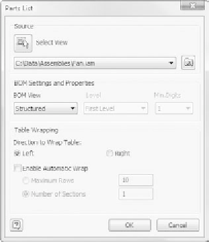
When the Parts List dialog appears, it asks you to pick a drawing
view. Pick the exploded view.
You have the option of creating a parts list that shows all the indi-
vidual parts or represents the structure of the assembly. The differ-
ence is, for example, that the fan support frame, which appears as a
single component in a Structured parts list, will appear as 12 parts
using the Parts Only BOM View option in the dialog.
4.
Leave BOM View set to Structured, and pick OK. If you receive a BOM
View Disabled dialog, click OK to enable.
A preview of the size of the parts list appears on the screen. Move
to the upper-right corner of the drawing border; a glyph appears,
showing that you can attach the parts list to the corner.
5.
Pick the upper-right corner to attach the parts list to the drawing.
The drawing looks like Figure 9.21 after you place the parts list.
6.
Look at the parts list as placed, and save your work.
The parts list that is placed may not look exactly like the parts lists you gener-
ally create. You may use different columns, and so on; but using styles and stan-
dards, you can set the parts list to look like those you've been creating for the
production people for years. You don't have to tell them that it now takes you
only a second to create the list — and I won't tell either.
Now, let's include the balloons you need to clarify where components are
located in the drawing view.


Search WWH ::

Custom Search