Graphics Programs Reference
In-Depth Information
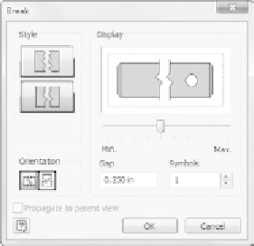
The Break View
The Break tool is useful for creating views in which you need to see details at
either end of an object but not what's in the middle. For example, you might use
it to detail a long shaft, removing most of the length from the middle. To create
the break, you defi ne two points: the beginning and the endpoint of the portion
of your part that will be removed from the view.
The Break dialog box allows you to defi ne how the break appears. Similar to
the Hole dialog box, it offers a preview that is representative of how the view will
be generated:
Style
The Style buttons let you choose between the Structural style, which
is a traditional border line with a single slash representing the break, and the
Rectangular style, which creates a fractured look. The preview on the right
changes to refl ect your selected style.
Orientation
This option establishes whether the break lines are horizontal or
vertical.
Display
The slide bar under the preview changes the size of the symbol at the
point of the breaks.
Gap
The Gap value specifi es how far apart the symbols and break lines are held
from each other.
Symbols
This option box defi nes how many symbols appear on the line with the
Structural break style.
Propagate to Parent View
This option is available only when the break is applied
to a projected drawing view.


Search WWH ::

Custom Search