Graphics Programs Reference
In-Depth Information
2.
Select the square in the sketch for the boundary.
3.
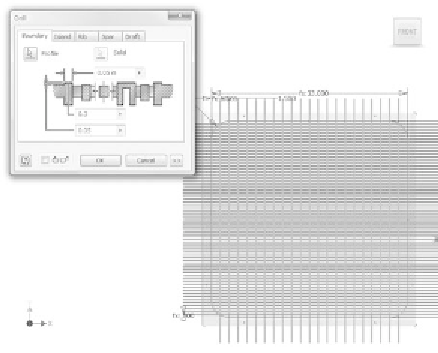
Set the width of the Boundary feature to be
0.05
, the height to be
0.3
,
and the offset from the sketch face to be
0.05
, as shown in
Figure 8.65.
FIGURE 8.65
Setting the values for the boundary
4.
Click the Rib tab.
5.
Drag a crossing window (right to left) across only the orange and
red lines.
6.
Set the rib width to be
0.05
, the height to be
0.25
, and the offset to
0
,
as shown in Figure 8.66.
It's important that you verify that only the appropriate lines are
selected for the rib.
7.
Click OK to create the Grill feature in the part. The fi nished part
should look like Figure 8.67.
8.
Save the fi le, and close it.
You've now created all the components you need for your design. Next, you'll
add the grill to the assembly and secure them in place.


Search WWH ::

Custom Search