Graphics Programs Reference
In-Depth Information
In Chapter 4, “Working with Solid Models and Weldments,” you used the
Rectangular Pattern tool to create a pattern of Hole features. Some additional
options are available for both the Rectangular Patter and Circular Pattern tools.
Let's do a quick review of the Circular Pattern tool.
The Circular Pattern Tool
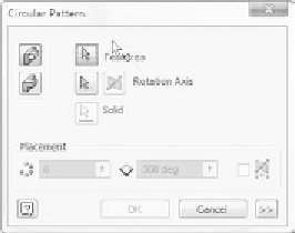
Circular patterns are very simple to create (see the dialog box in Figure 8.43),
but it's also easy to overlook a couple of important options:
FIGURE 8.43
The Circular Pattern dialog box
Pattern the Entire Solid
Typically, you can select a few features that you want
to pattern. The Pattern the Entire Solid option is great if you want to develop a
part that has symmetry. This works for either rectangular or circular patterns
as well as the Mirror tool. Whereas patterning individual features has Inventor
calculate the new pattern members (instances), patterning the entire part cal-
culates more quickly.
More
For the Circular Pattern tool, some important options are hidden under
the More button:
Optimized
The most important is the Optimized option. This option
ignores feature calculations and replicates the body of the features
rather than their values.
Incremental
The default value for Positioning Method is Fitted. This
applies the number of features evenly across the angle entered in the
main part of the dialog. The Incremental option causes an angle
value to be the angle between instances.
Let's complete the major portion of the component using a circular pattern.


Search WWH ::

Custom Search