Graphics Programs Reference
In-Depth Information
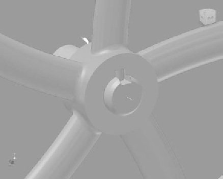
FIGURE 7.42
Drag the length. Note that it steps only in standard lengths.
12.
Compare your preview with Figure 7.42 and click OK to make the
modifi cations to the shaft and pulley and generate the key.
13.
The fi nished geometry should look like Figure 7.43.
FIGURE 7.43
The completed key and grooves
14.
Double-click the pulley to activate it in the context of the assembly.
You should see a groove and the diameter of the shaft cut from the
pulley.


Search WWH ::

Custom Search