Graphics Programs Reference
In-Depth Information
Each shaft section has four icons that control the beginning condition, the
section shape, the end condition, and any special geometry on the section. After
the icons is a listing of the section's size and general shape. Each icon has a
pull-down you can use to select the shape. Clicking one of the icons lets you
change the values associated with that shape.
The remaining shaft section (Figure 7.8) begins with a chamfer and a cylinder
and ends with a fi llet. The size is presently 2 inches in diameter by 4 inches in
length.
FIGURE 7.8
Each shaft section is controlled by a row of icons.
7.
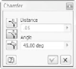
Click the chamfer on the left end of the shaft section. This brings up
the Chamfer dialog.
8.
Change the Distance value to
.05
. Pick the check mark to close the
dialog.
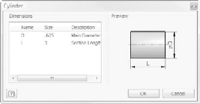
9.
Click the cylinder, and set the Diameter value to
.625
inches and the
Length value to
3
inches in the dialog. Click OK to close the dialog.
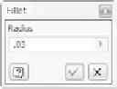
10.
Edit the fi llet on the right end of the section. Set its Radius value to
.03
inches. Click the check mark to accept the change.
11.
In the dialog, pick the Cylinder icon next to the sections pull-down.
Doing so adds a new cylindrical section to the shaft. The fi llet that
you just edited disappears because the new section is the same diam-
eter as the fi rst.


Search WWH ::

Custom Search