Graphics Programs Reference
In-Depth Information
14.
Zoom out so you can see the left side of the housing.
15.
Drag the endpoint of the tangent line to make it about half as long as
the assembly is wide. Press Esc to end the Dimension command if
needed.
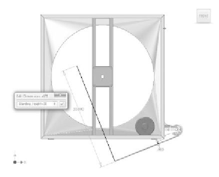
16.
Draw a perpendicular line starting on the end of the fi rst line, as
shown in Figure 6.50.
17.
Dimension the line's length to a value of Standing_Height=30, as
shown in Figure 6.50.
FIGURE 6.50
Adding the perpendicular line
This new line sets the target height for the handle from the fl oor
when the person moving it is standing. It also creates a named param-
eter that will make it easier to locate and modify in the Parameters
table.
18.
Create a Coincidence constraint between the endpoint of the 30in.
line and the left, vertical edge of the housing. See Figure 6.51. Be
sure not to pick the midpoint of the edge.
19.
Add a dimension between the endpoint of the 30in. line and the point
you projected early on. Click to place the dimension.
When you attempt to place the dimension, you receive a warning
that the dimension will “over-constrain” the sketch. You're offered a
chance to place the dimension as a driven dimension. You want this
dimension to be driven because it's going to provide you with the dis-
tance you're looking for.


Search WWH ::

Custom Search