Graphics Programs Reference
In-Depth Information
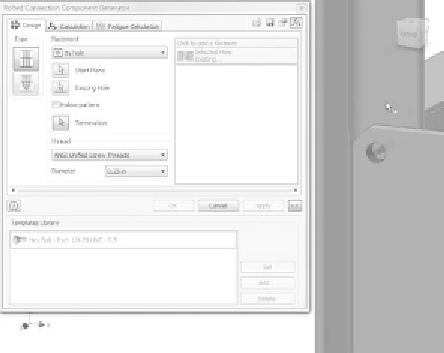
FIGURE 5.29
Select the placement of the new bolted connection.
8.
Set the Follow Pattern option to On, and click OK to create the new
set of bolted connections shown in Figure 5.30.
9.
Save your work.
10.
Select the tab for viewing the fan assembly at the bottom of the
Design window.
11.
Pick the Update icon in the Quick Access Toolbar to make sure the
assembly is up to date and review the changes that have been made.
The assembly should look like Figure 5.31.
FIGURE 5.30
Adding the rest of the bolted connections


Search WWH ::

Custom Search