Graphics Programs Reference
In-Depth Information
You're now fi nished building the frame. As you notice in the dialog boxes, it's
possible to include gaps for welding in the joints and when trimming members.
The Frame Generator has been a huge hit with users who need to create frames
of nearly any shape. If you have a need for this tool, I encourage you to explore
the options further.
To fi nish the assembly, you'll bring in the bearing supports that you created in
the last chapter.
Adding the Bearing Supports
The function of this frame is to hold the bearing supports, which in turn will
hold the shaft that the fan blade will be mounted to. So, it makes sense for the
bearing plate to be mounted to the frame.
1.
Return the Ribbon to the Assemble tab, if it didn't switch
automatically.
2.
Click the Place tool. In the resulting dialog, select Bearing Support
from the Assemblies folder, and click Open to insert it in the
assembly.
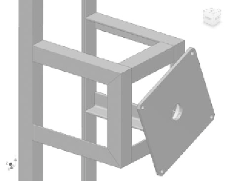
3.
Create a constraint between the axis in the bearing support and the
Z axis of the assembly. See Figure 5.19.
FIGURE 5.19
Beginning to assemble the bearing support onto the frame
4.
Place a Mate constraint between the back of the frame and the front
of the bearing plate.


Search WWH ::

Custom Search