Graphics Programs Reference
In-Depth Information
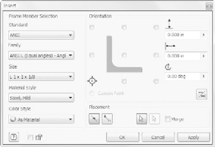
FIGURE 5.9
The Frame Generator's Insert dialog box
Frame Member Selection
In the Frame Member Selection group, you select the
Standard you wish to work in and the type or Family of shapes you're looking
for. After you've selected a family, you need to choose from the available sizes.
You can also select a Material for the components and choose to override the
color with something other than that of the material if you like.
Orientation
When you've selected the frame member information, a preview is
available on the right. There are 10 points surrounding the profi le, which you
can use to modify the location. Selecting a point establishes how the member
will be oriented when you've chosen the Placement. You can make more adjust-
ments using the dimensional offsets to the right of the preview. The angle can
also be changed.
A button beneath the angle value allows you to mirror the profi le. This is a
nice improvement over having to set angle values of more than 180 degrees to
properly align members.
Placement
You have two options for placing members: selecting one segment,
be it a line, an arc, or a model edge; or selecting two points that can be along
lines or on a model.
The fi nal option under Placement is a Merge check box. In cases where you
select arcs that have other arcs or straight portions tangent to them, the Frame
Generator separates the portions of the frame. The Merge option binds the tan-
gent members together.
At lower left, next to the Help icon, is a switch that specifi es whether Inventor
prompts you with the naming of the fi les that are created.


Search WWH ::

Custom Search