Graphics Programs Reference
In-Depth Information
After adjusting a view location or two, it looks like you're in good shape to be
able to detail your assembly. Let's make a couple more views. As with the Modeling
and Assembly tools in Inventor, once you've made a couple of types of drawing
views, the others seem to come naturally.
Creating Section Views
Section views are essential for many kinds of drafting and design. The Section
View tool in Inventor allows you to defi ne your section view using one or more
straight segments and arcs that pass through the part. You can defi ne the
sec-
tion line
to have a relationship with geometry in the drawing view. There is no
limit to the number of section views you can place on a view, and the section line
doesn't have to pass entirely through the parent view to build a section view.
Defining the Section View
For this exercise, you'll create a basic section view. Section views can also be
created with a section line in several segments:
1.
Zoom into the base view so that you can see space beneath it in the
Design window.
2.
Start the Section tool in the Create panel.
3.
Select the base view to see the prompt “Enter the endpoints of the
section line” on the status bar.
4.
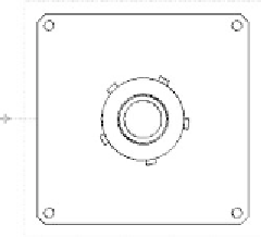
Gesture over the large hole in the center of the view, and then move
to the left. You see a dotted line infer the center of the hole. As you
move outside of the part perimether, the inference line may show the
midpoint of the side of the part. Either is acceptable. See Figure 4.41.
FIGURE 4.41
Inference lines help guide you when placing section lines.


Search WWH ::

Custom Search