Graphics Programs Reference
In-Depth Information
When you project the edge, a special icon appears next to the sketch
in the Browser and next to the name of the part in the Browser to
indicate that geometry in that sketch is adaptive to changes in other
parts. The sketch appears simple, showing the edge of the hole and a
center point; but this geometry will move if the hole changes size or
location in the duct.
6.
Repeat step 5 for the remaining holes in the duct.
7.
Finish the sketch.
8.
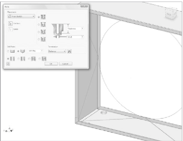
Start the Hole tool, and pick the center points on the three projected
circles for the Placement.
9.
The hole depth is again automatically set to Thickness.
10.
Enter
9/64
for the Diameter value. Inventor does the math for you.
This is the proper pilot-hole size for a #10 sheet metal screw. Review
Figure 3.36.
11.
Click OK to create the holes in the housing.
FIGURE 3.36
Creating the holes located in the duct part


Search WWH ::

Custom Search