Graphics Programs Reference
In-Depth Information
or Angle constraint, the values of those constraints are automatically fi lled in
with their current position; otherwise, Inventor would snap the parts tightly
together, and you'd have to experiment with values to return them to the posi-
tion they're already in.
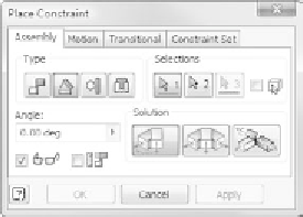
Also notice the Solution area. As you'll see, the solution you can apply will
depend on the type of constraint you're applying.
Let's look at the groups in the dialog box and go through some of the options.
Type
The Type group has four primary ways of defi ning an assembly constraint: Mate,
Angle, Tangent, and Insert. Using these tools, you can build any rigid assembly.
Mate, the fi rst type of constraint (the highlighted box under Solution), has
two solution options. The Mate solution applies an oppositional force. It emu-
lates elements being stuck together. A mate can also be applied between any
combination of points, edges (axes), and faces. The other solution, Flush, can
only be applied between faces; it's used to align faces that are parallel to one
another.
An Angle constraint defi nes nonparallel aligned conditions. It can only be
placed on edges and faces. There are three solutions for the constraint. The
default solution is the Directed Angle; it applies a positive value clockwise about
its axis. The Undirected Angle solution can apply a positive value about the axis
in either direction. If parts unpredictably change orientation, try changing the
angular constraint used on the parts to this solution. The third solution is Explicit


Search WWH ::

Custom Search