Graphics Programs Reference
In-Depth Information
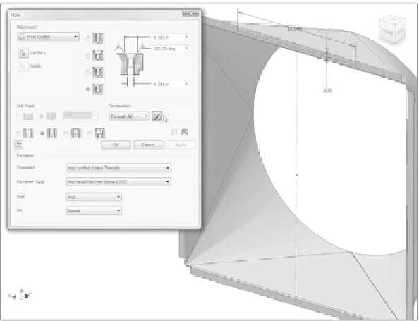
FIGURE 3.22
Placing the mounting holes in the duct
So far, the instructions for the exercises have had you build parts correctly.
(The same will be true for most of this topic.) In this exercise, I deliberately had
you construct the primary feature, the lofted fl ange, using an incorrect size.
When you created the sketch and work plane for the circle, you did so at a dis-
tance of 12in. This is the same width as the housing, which doesn't leave a lot of
room for a fan blade or anything else. Let's correct this error now:
1.
Locate Work Plane 1 in the Browser.
2.
Double-click the icon. A dialog appears, showing the distance the
plane was defi ned by. The plane also highlights.
3.
Set the value for the plane to 8in., and use the check mark to accept
the new value. See Figure 3.23.
4.
This type of modifi cation doesn't cause the model to update. Instead,
the Update icon appears on the Quick Access Toolbar.
5.
Click the Update tool. The model then recalculates. See Figure 3.24
to compare your result.


Search WWH ::

Custom Search