Graphics Programs Reference
In-Depth Information
FIGURE 3.4
The Lofted Flange dialog
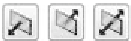
When you created a contour fl ange and a regular fl ange, you may have
noticed three icons with arrows in the dialog boxes. Selecting one of these
icons will defi ne which side of the sketch or selected edge your material is
added to or whether the material's thickness is divided equally on each side.
You'll also see these options on many of the tools on the Model tab. It's impor-
tant to verify that your material is being added to the side that you want, or
your overall component size may be affected.
Output Options
The Output group in the dialog contains two primary options. You need to know
how this part will be manufactured, to select the option properly:
Die Formed
Selecting this option creates a transition where the bent portions
are created as a single bend. This requires a more specialized manufacturing
process, but the result is a smoother part. Selecting this option also disables the
Facet Control options.
Press Break
If the part will be manufactured using a press break, and if having
the transition formed in steps or facets is acceptable, then you should use this
option. Picking the Converge check box lets Inventor blend the facet edges
together at the end where they meet.
Facet Control
Three options defi ne how large and how many facets make up
the bent portions of a transition. They're called out by a letter and name. The


Search WWH ::

Custom Search