Graphics Programs Reference
In-Depth Information
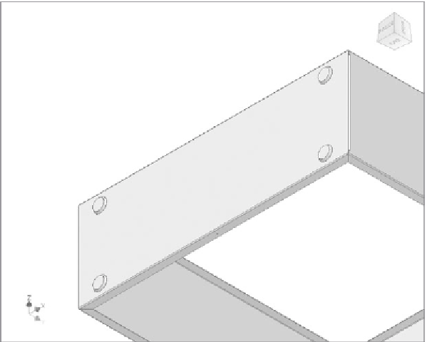
FIGURE 2.56
The completed Punch tool feature has added feet to
the housing.
18.
Return to the home view.
19.
View the fl at pattern. The cut and the hole feature are visible, but the
Punch tool features aren't. This is because the sheet metal rule says
that this type of feature is displayed in the drawing as an outline and
center mark so it isn't left as a 3D feature in the fl at pattern.
20.
Zoom in on the cut feature.
21.
Switch to the Tools tab, and start the Distance measurement tool.
22.
Click the horizontal edge beneath the cut. A value appears in the
Measure Distance dialog. This is the length of the selected edge.
23.
Move near one of the bottom corners of the rectangular cut. A small
circle appears around the corner. When it does, pick again.
The dialog box that shows the length of the edge now displays the
minimum distance between the entities. You'll see that the distance
is 0.6 in (Figure 2.57), which is what you dimensioned it to be while
previewing the fl at pattern.


Search WWH ::

Custom Search