Hardware Reference
In-Depth Information
Memory control signals (rd, wr, fetch)
3
4
4-to-16
Decoder
MAR
MDR
MPC
9
PC
O
8
MBR
512
×
36-Bit
control store
for holding
the microprogram
SP
9
LV
JMPC
MIR
CPP
Addr
J ALU
C
M B
TOS
JAMN/JAMZ
OPC
H
High
bit
Bbus
2
Control
signals
1-bit flip-flop
N
6
ALU
control
ALU
Enable
onto
Bbus
Z
Shifter
2
Cbus
Write
Cbus
to register
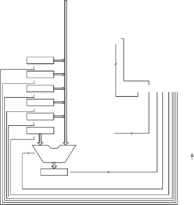
Figure 4-6.
The complete block diagram of our example microarchitecture, the Mic-1.
In one important way, the control store is quite different from the main memo-
ry: instructions in main memory are always executed in address order (except for
branches); microinstructions are not. The act of incrementing the program counter
in Fig. 2-3 reflects the fact that the default instruction to execute after the current
one is the instruction following the current one in memory. Microprograms need
more flexibility (because microinstruction sequences tend to be short), so they
usually do not have this property. Instead, each microinstruction explicitly speci-
fies its successor.
Since the control store is functionally a (read-only) memory, it needs its own
memory address register and memory data register. It does not need read and write