Information Technology Reference
In-Depth Information
Main
Element_*
Window_d
line
rectangle
circle
canvas
getStart()
getEnd()
getULCorner()
getLRCorner()
getCenter()
assignLine()
assignRectangle()
assignCircle()
CreateButtons()
addLine()
addRectangle()
addCircle()
mousePresed()
mouseReleased()
Draw()
isLineSelected()
isRectangleSelected()
isCircleSelected()
Element_d
line
rectangle
circle
implementation
Mouse
RadioButton
Line_d
start
end
setStart()
setEnd()
Rectangle_d
Circle_d
Canvas
upper_left
lower_right
center
radius
setULCorner()
setLRcorner()
setCenter()
setRadius()
Legend:
Classes provided
by specific
languages
(i.e JAVA)
Point
Double
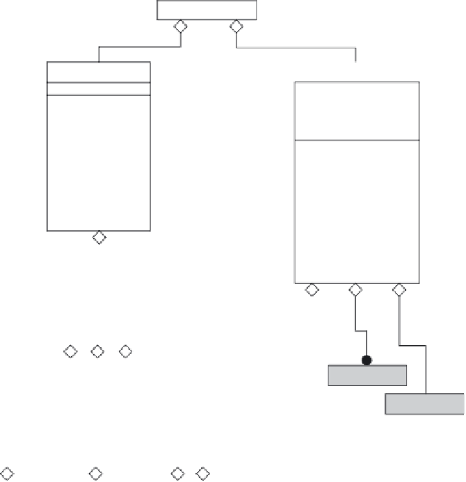
FIGURE 13.10
Object-oriented model generation.
The same rule can be introduced to represent the interface information such
as aggregation, generalization, and so forth in the design matrix for DP/PV
mapping. Figure 13.10 shows a class diagram for this example based on the
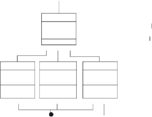
matrix for DP/PV mapping. The flow diagram in Figure 13.11 shows the
developing process depicting how the software can be programmed sequen-
tially.
g. Table 13.3 categorizes the classes, attributes, and operations from Figure 13.9
using this mapping process. The first row in Table 13.3 represents the PV.
The sequences in Table 13.3 (i.e., left to right) also show the programming
sequences based on the flow diagram. Figure 13.11 shows classes diagram for
this example based on the matrix for DP/PV mapping.


Search WWH ::

Custom Search