Information Technology Reference
In-Depth Information
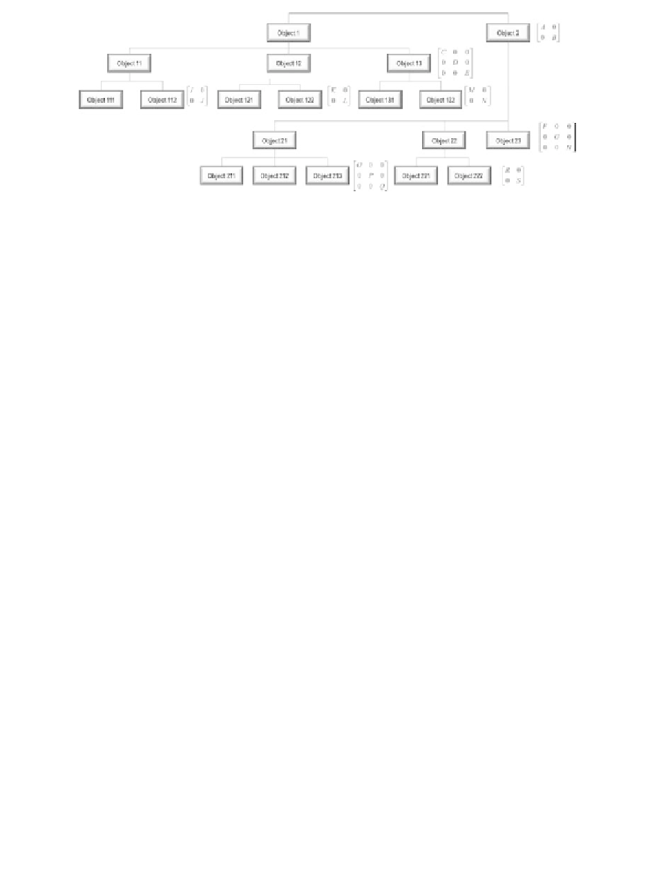
FIGURE 13.7
The design hierarchy.
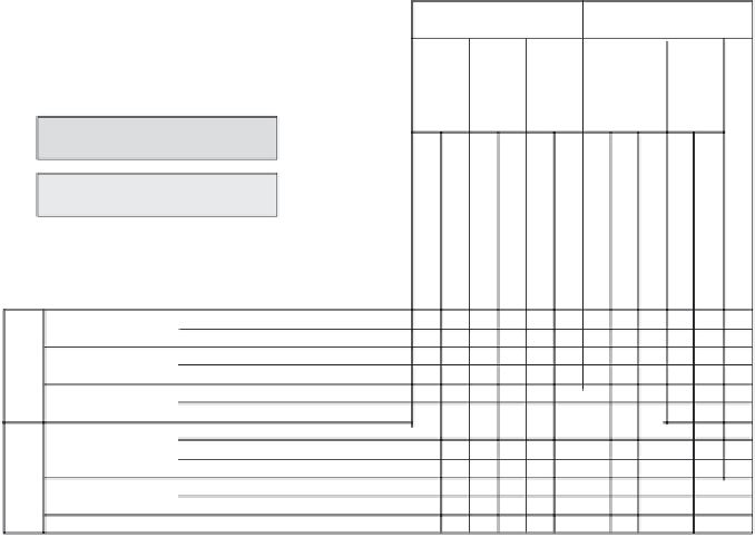
The fulldesign matrix shown in Figure 13.8 indicates that the design has no
conflicts between hierarchy levels. By definition, each row in the full-design
matrix represents a module to fulfill corresponding FRs. For example, FR
23
(draw an element) only can be satisfied if all DPs, except DP
221
and DP
222
,are
present.
e. Identify objects, attributes, and operations: Figure 13.9 shows how each design
matrix elements was transformed into programming terminology. Unlike the
other design cases, the mapping between the physical domain and the process
DP1: Element
characteristics
DP2: GUI with window
DP12:
Rectan
gle
charact
eristic
DP22:
Mouse
click
inform
ation
DP11:
Line
charact
eristics
DP13:
Circle
charact
eristic
On-diagonal element for the
intermediate or higher level
DP21:
Radio
buttons
Off-diagonal element for the
intermediate or higher level
Off-diagonal element for the leaf
or lower level
FR11: Define line
element
FR111: Define start
I
C
A
J
FR112: Define end
FR121: Define upper left corner
FR122: Define lower right corner
FR131: Define center
FR132: Define radius
FR211: Identify line
FR212: Identify rectangle
FR213: Identify circle
FR221: Detect mouse push
FR222: Detect mouse release
D
K
FR12: Define
rectangle element
FR13: Define
circle element
L
M
E
N
O
F
B
FR21: Identify the
drawing type
FR22: Detect
drawing location
FR23: Draw the element
P
b
Q
X
X
X
XX X
R
G
XXXX
S
X
X
XX X
X
X
XXXX
H
c
a
FIGURE 13.8
The full-design matrix.


Search WWH ::

Custom Search