Information Technology Reference
In-Depth Information
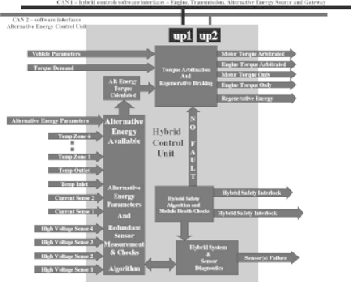
FIGURE 10.11
Hybrid control unit design architecture.
Figure 10.11 shows the details of the hybrid control unit design proposed architec-
ture. In this design, four high-voltage sense lines for sensing high voltage, two current
sensors for sensing current, six temperature sensors to sense six zones, an inlet tem-
perature sensor, and an outlet temperature sensor were interfaced with the alternative
energy redundant sensor measurement block. In addition, various alternative energy
parameters were fed to this block for redundancy checks as well as for precise cal-
culation of energy available from an alternative energy source. A sensor diagnostics
block was designed to perform a power-on sensor health and a periodic sensor health
check and to report sensor errors upon detection. If sensors were determined to be
good, and no hybrid and motor safety interlock fault or ECU health check faults were
set, then a “NO FAULT” flag was SET. Depending on the alternative energy available,
available alternative energy torque was calculated and fed to the “torque arbitration
and regenerative braking” algorithm block. In addition, vehicle parameters such as
rpm, vehicle speed, acceleration, deceleration, emergency situation parameters, and
vehicle torque demand also were fed to this block to calculate the arbitrated torque
required from the motor and the engine. Three hybrid-operating modes were deter-
mined for which four required torques were calculated, which were Motor Torque
Only, Engine Torque Only, Motor Torque Arbitrated, and Engine Torque Arbitrated.

Search WWH ::

Custom Search