Biomedical Engineering Reference
In-Depth Information
place. To allow for manufacturing differences and the use of different length cantilevers,
there is usually some room for manoeuvre in where you place the chip, usually just a few
hundred micrometres. It is not possible to put the chip in the same place each time by hand,
and even a few tens of micrometres will completely change the optical alignment required.
It is sensible therefore to find a position that works and stick with it, in this way the
realignment on changing the probe will be minimal. Some users find that placing the chip
against the edges of the slot can give increased stability and more reproducibility of the
chip position. Some alternative instrument designs use either pre-mounted cantilevers on
larger 'cartridges', or alignment groves machined into the cantilever chips to help in
placing the chip, but most rely on the manual insertion approach described above.
4.2.1 Optical alignment
After placing the probe in the instrument, the alignment of the optical lever is carried out.
This is done in two stages. Firstly, the laser spot is adjusted onto the end of the cantilever.
There will usually be two screws to adjust for this, one to move the laser parallel to the
cantilever axis, and the other perpendicular. The exact procedure for the alignment can
differ somewhat from instrument to instrument, depending on the view the user has of the
cantilever and laser spot on the optical inspection scope. The user must take care not to
look directly into the laser beam, as it can easily damage the eyes. Visualization of the
laser spot can be done by placing a piece of white card or paper in the path of the laser.
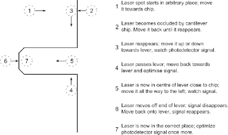
A general procedure for alignment of the laser beam is shown in Figure 4.3. Figure 4.3
shows the procedure for beam-shaped cantilever. For v-shaped cantilevers, the procedure
is very similar but at steps 4-5 the laser spot is positioned between the cantilever legs.
Fig. 4.3. Laser alignment procedure.