Biomedical Engineering Reference
In-Depth Information
3.2.5 Electric force microscopy and scanning Kelvin probe microscopy
Electric force microscopy (EFM) refers to a technique analogous to MFM which enables
the measurement of electrical fields with the AFM, rather than magnetic fields. Essen-
tially, the technique can be applied by carrying out experiments in a lifting mode as
described above, but without a magnetic coating on the cantilever. A standard silicon or
silicon nitride cantilever may be used for simple EFM imaging, although conductive
(metal-coated) tips are required for read/write applications, and more sophisticated elec-
trical modes (see below). The equation for electrostatic forces between a probe and a
surface having different potentials is given by:
2(V)
2
dC
dz
F
electrostatic
¼
1
=
ð
3
:
3
Þ
It can be seen that from Equation 3.3 and Equation 3.2 that the change in resonant
frequency is proportional to the changes in capacitance as a function of the second
derivative of
z
spacing. In other words, as long as there is a non-zero potential between
the probe and surface, the frequency, and thus the amplitude and phase of oscillation will
be sensitive to capacity of the surface.
EFM has been shown to detect trapped charge on surfaces [222], and in some cases
gives clear contrast where none is visible in the topography signal. However, it has been
reported that EFM is prone to topographic artefacts [223]. EFM, like MFM has the great
advantage that it may be carried out with a standard AFM. A somewhat more sophisticated
technique to measure tip-sample potential is scanning Kelvin probe microscopy (SKPM)
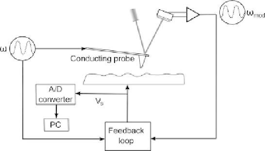
[224, 225]. Figure 3.23 illustrates the portion of the SKPM instrument used for equilibrat-
ing the probe surface potential. The electronics used for mechanically vibrating the
cantilever are not shown.
The principle of operation of SKPM is simple, that is when two surfaces have the same
potentials, there will be no forces between them, so in Equation 3.3,
0. To
implement the technique, a DC potential bias (
V
DC
)
is applied to a conductive probe,
which is further modulated by an AC signal (
V
AC
), so that
˜
V
¼
Fig. 3.23. Schematic illustration of instrumental set-up for scanning Kelvin probe microscopy.