Biomedical Engineering Reference
In-Depth Information
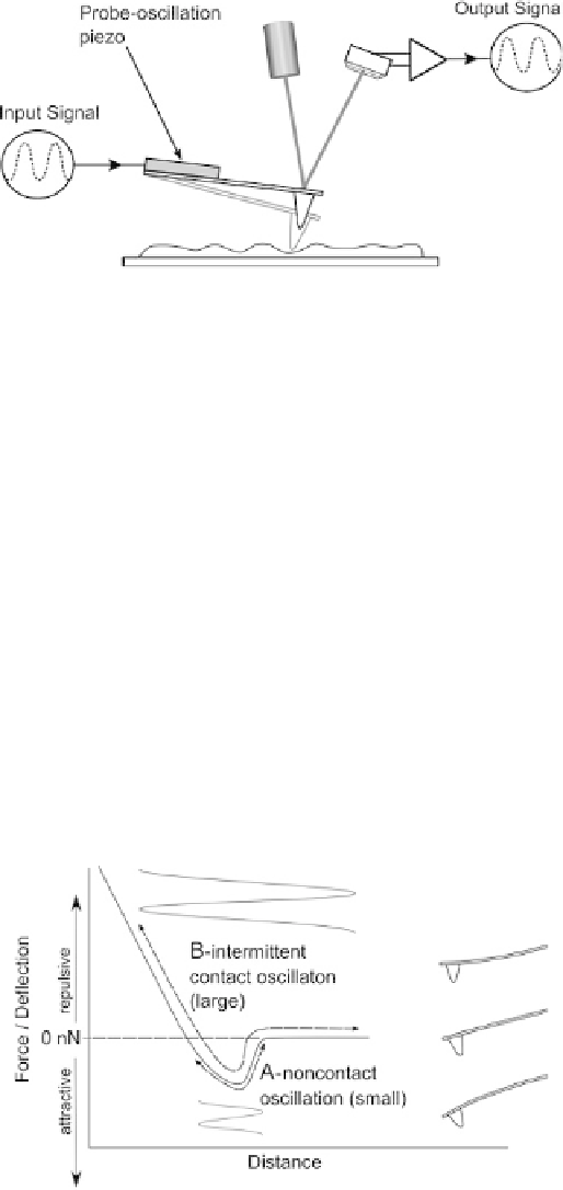
Fig. 3.5. Schematic of generalized operation of oscillating AFM modes, showing instrumental
set-up. An oscillating input signal is applied to the cantilever to make the probe vibrate up and
down. The actual movement of the probe will depend on its interaction with the sample surface. The
resulting oscillation in the cantilever deflection is measured and compared to the input oscillation to
determine the forces acting on the probe.
the cantilever in the attractive regime only. This technique is sometimes known as non-
contact AFM, or alternatively, and perhaps more accurately, as close-contact AFM (see
Table 3.1). This technique has some advantages due to the low probe tip-sample forces
involved, and is discussed below in Section 3.1.2.1. On the other hand, it can be seen that
if a large oscillation amplitude is applied, then the probe will move from being far from
the surface where there's no tip-sample interaction, through the attractive regime, into
the repulsive regime, and back, in each oscillation cycle (arrow B). This technique
involves large probe tip-sample forces, so can be more destructive, but is easier to
implement. This technique is what we call intermittent contact-mode AFM (and is also
known by many other names, some of which are given in Table 3.1), and is discussed in
Section 3.1.2.2.
Fig. 3.6. Different operating regimes for oscillating AFM modes. A: with a small amplitude of
oscillation, the probe can be kept in the attractive regime. B: with a larger oscillation the probe
moves through non-interacting, attractive and repulsive regimes, resulting in intermittent contact.