Biomedical Engineering Reference
In-Depth Information
Fig. 2.27. Illustration of an AFM cantilever/probe/substrate created by micromachining of Si or
Si
3
N
4
. All commercially available probes have substrates with the same dimension, for ease of use in
different instruments. The probe is sometimes referred to as the tip, and the substrate as the chip. Not
to scale.
disposable component of the AFM. In principle, an AFM probe should last forever;
however, in practice the probe tip is often blunted when it touches a surface. Changing
the probe typically takes only a few minutes. In order to make handling simple, the
cantilevers are attached to a cantilever substrate or chip. By industry convention, these
are normally
ca
. 3.5
1.6 mm in size, and about 0.5 mm thick, so that probes from
different manufacturers can be used in most probe holders built into AFMs. Figure 2.27
shows a cartoon of the design of a typical probe/cantilever/substrate.
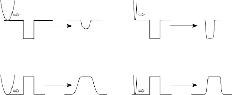
The geometry of the probe is critical to the quality of images measured with an AFM.
All AFM images are a convolution of probe geometry and surface. As an example, in
Figure 2.28, if the probe cannot reach the bottom of a surface pit, or track the sides of a
particle, the image will not indicate the correct geometry of the sample. Further details on
the problems associated with blunt tips are shown in Section 6.1.
2.5.1 Probe materials
In principle, AFM cantilevers can be fabricated from any material that can be fabricated into
a spring-like cantilever. The first AFM cantilevers were fabricated from tungsten wire and
Fig. 2.28. Comparison of image profiles obtained with a dull (left) or a sharp (right) probe on a
concave feature (a pit, top) or a convex feature (a step feature, bottom).