Biomedical Engineering Reference
In-Depth Information
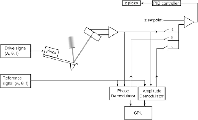
Fig. 2.24. Block diagram of the electronics employed for oscillating mode AFM scanning. The
signal used for feedback can be selected by switch a, b or c. Switch a is for DC feedback, b for phase
feedback, and c for amplitude feedback.
In an AFM there is typically one or more high-speed analogue to digital converters (ADC).
If there is a single ADC, the many analogue signals are passed through a multiplexer into
the ADC input (see Figure 2.21). The speed of the A/D converter must be high enough
such that at least one data point is converted per pixel.
Note that bit noise, as described in the section about
x-y
scanning, is also important
in the context of the acquisition of the
z
axis data i.e. the
z
voltage signal. Although the
z
piezo range is typically much lower than the
x-y
range (typically, a large
sample AFM scanner might have a
z
range of 10
m),
the achievable resolution in
z
is also much greater than in the
x-y
plane. If we imagine
the case above, then with 10
mandan
x-y
range of 100
m
z
range a 16 bit ADC would limit us to 10,000
angstroms/65,356 bits
1.4 angstroms per bit. This is much greater than the resolution
of a modern AFM, which might be expected to show
¼
0.5 angstrom root-mean-
squared (rms) noise in
z
under typical conditions. This bit noise can significantly
degrade results when scanning small features on a very flat surface, or carrying out
sensitive force spectroscopy experiments. Typically, to overcome this, the AFM allows
a similar 'scale and zoom' solution; the
z
bit resolution is increased temporarily by
only using a part of the
z
piezo range. This setting is typically applied by the AFM
operator, rather than automatically. This is because it should only be used with flat
samples and small scans, as it is not advantageous to reduce the
z
range while scanning
rough samples.
<