Biomedical Engineering Reference
In-Depth Information
Fig. 2.19. Left: video camera image of the cantilever and sample in an AFM (90
8
top view). The red
'spot' is from the laser that is used in the optical lever force sensor. With scanning ranges greater
than 1
m, it is possible to see the AFM cantilever move in the video microscope image. Middle: the
three possible viewing positions of an optical microscope in an AFM. Right: image in an AFM with
90
8
bottom view; note the laser light (purple in this case) can be seen through the cantilever, which is
seen through the sample (cells on a glass slide). (A colour version of this illustration can be found in
the plate section.)
2.2.6 Mechanical loop
The greatest factor that affects the vertical resolution or noise floor of an AFM is the rigidity
of the mechanical loop. The mechanical loop is comprised of all the mechanical elements
between the sample surface and the probe, as illustrated in Figure 2.20. If this loop is not rigid,
then the probe can vibrate in an uncontrolled manner relative to the sample, and noise is
introduced into images. It is typically easier to make the mechanical loop very rigid by
making the microscope very small. Because of this, in practice the highest resolution AFM
instruments are very small. It alsomeans that it is very difficult tomake AFMstages for larger
samples such as silicon wafers or optical disks that have very high vertical resolutions.
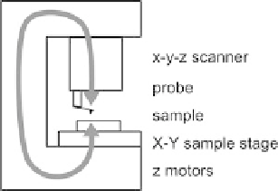
Fig. 2.20. The mechanical loop in an AFM includes all of the structural elements that are required to
hold the probe at a fixed distance from the sample. This includes the x-y-z scanner,
X-Y
sample stage,
Z
motor and the probe.
Most of the electronics in an AFM are resident in a separate cabinet from the stage and the
computer. The functions in the electronic controller may be constructed with digital signal