Biomedical Engineering Reference
In-Depth Information
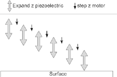
Fig. 2.17. 'Woodpecker' probe approach method. The surface is approached by alternately expand-
ing the piezoelectric element, and stepping the
z
motor. This avoids uncontrolled contact between the
probe and the sample. As soon as the surface is encountered, the feedback system is turned on.
In the AFM stage there are two separate motion generation mechanisms in the
Z
axis.
The first is a stepper-motor-driven mechanism with a dynamic range of a centimetre and a
resolution of a few microns. The stepper motor is driven either by a linear bearing or an 80
turn per inch screw. The second motion generation mechanism in the
Z
axis is the
z
piezoelectric element in the AFM scanner. The
z
piezo typically has a dynamic range of
about 10 microns or less and a resolution of less than 0.5 nm. While stepper motors have
the range and speed to approach the surface from a great distance in a short time, they
have neither the resolution nor fast response time to put the tip into feedback safely. On the
other hand, the piezo driver is sensitive enough to safely go into feedback, but can only
move short distances.
Typically, probe approach is achieved with a 'woodpecker' method, (shown in
Figure 2.17). In this method, the stepper motor is stepped a small increment, say 1 micron.
Then the
z
piezoelectric ceramic is extended 5 microns to see if the surface is detected. The
z
piezo is then retracted, the stepper motor extends one more micron, so on and so on.
A key component here is that when the probe encounters the surface, the feedback is
turned on immediately. In this way, the AFM can approach the surface from several
hundreds of microns, without risk of crashing the tip.
There are two primary mechanisms that may be used for the
Z
motion control, as shown
in Figure 2.18. In the first, three lead screws are used together with a kinematic mount. All
three screws can be turned simultaneously or a single screw may be turned. If only one of
the screws is turned, there is a reduction of motion at the centre of the three screws. This
geometric reduction in motion can be used to get very precise motion. For automated tip
approach, one or all of the lead screws is attached to a motor. In the second method, a
linear bearing is used to drive the AFM scanner towards the sample. The linear bearing
must be very rigid to avoid unwanted vibrations.
2.2.4 Coarse X-Y movement
Most AFMs include an
X-Y
position stage for moving the sample relative to the probe. The
stage may be manual or automated with motors. The primary function of the
X-Y
stage is