Biomedical Engineering Reference
In-Depth Information
d
2
-
d
1
a
V
(2.1)
where
V
= voltage applied
d
1
d
2
-
d
1
a
´
V
(2.2)
t
where
V
= voltage applied
t
= tube wall thickness
L
2
(2.3)
d
a
´
V
t
where
V
= voltage applied
t
= bimorph thickness
L
= bimorph length
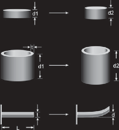
Fig. 2.8. Typical geometries for piezoelectric elements used in AFM. From top: piezoelectric disk,
tube and bimorph scanners.
Correcting the non-ideal behaviours of piezoelectric ceramics is essential for making
accurate measurements with an AFM. Due to the different ways the axes are operated -
x
and
y
in a raster pattern,
z
moved by the feedback control - the corrections required are
different for the
x-y
axes and the
z
axis. Also, hysteresis and creep make it difficult to scan
the AFM very quickly, and maintain accuracy. The non-ideal motions of piezoelectric
ceramics may be corrected using open-loop or closed-loop methods [31]. The following
sections describe the typical methods used to correct for non-linearities in piezoelectric
scanners.
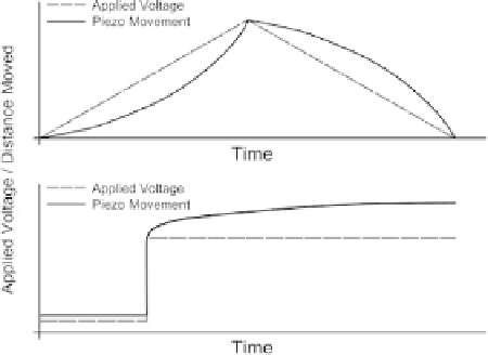
Fig. 2.9. Examples of non-linear behaviour in piezoelectric scanners. Top: hysteresis; when a
voltage ramp is applied to the piezo, the response is non-linear. Bottom: creep; after an impulse
applied to the piezo, the movement continues in the same direction.