Biomedical Engineering Reference
In-Depth Information
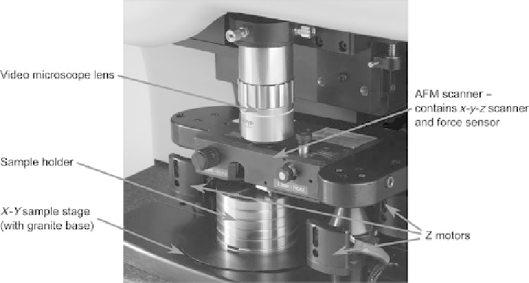
Fig. 2.6. Photo of an AFM stage, with components highlighted.
• A high-speed computer that can display the images in real time as they are collected
must be used.
• A stage that allows rapid exchange of the probe used for scanning must be created.
The ways in which these challenges are overcome are discussed in the following sections
of this chapter.
The AFM stage is the heart of the instrument; Figure 2.6 shows an AFM stage and
highlights the major components. There must be probe and sample holders. There is a
coarse approach mechanism, the
Z
motor, which can move the AFM scanner towards the
sample. There is also an
X-Y
positioning stage which is not required but is useful for
positioning the feature for imaging under the probe. To help with this, there is usually an
optical microscope for viewing the probe and surface.
A mechanical structure is required to support the AFM scanner and other components.
In the construction of the stage it is important that the mechanical loop, which contains all
the mechanical components between the probe and surface, be very rigid. If the mechan-
ical loop is not rigid, then the probe will vibrate relative to the sample and introduce
unwanted noise into the images.
In general, if the microscope stage is smaller, it will be less susceptible to external
vibrations. Creating a rigid mechanical loop becomes more difficult the larger the sample
size is. The highest resolution AFMs tend to be very small so that the mechanical loop is
rigid, and the microscope stage is not susceptible to external environmental vibrations (or
noise).