Biomedical Engineering Reference
In-Depth Information
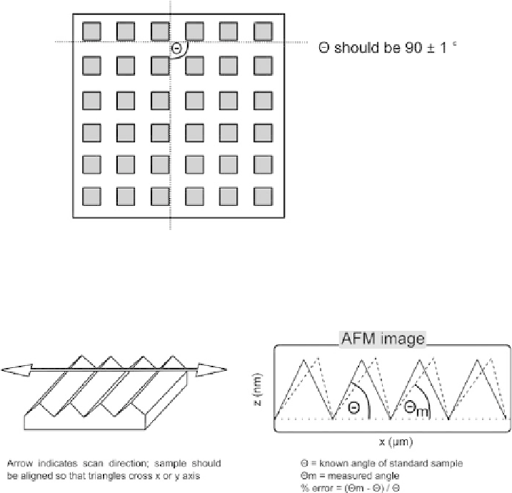
Fig. B5. Method to measure orthogonality between
x
and
y
scan axes.
Fig. B6. Procedure to measure the
xz
and
xy
crosstalk.
B3.2
xz and yz orthogonality
With the scan axis at a right angle to the ridges, an image is measured of the triangle
sample (see Appendix A). The angle is measure in software. There can be a substantial
deviation from the true angles due to the coupling between the
x-z
or
y-z
axes. This
measurement must be done twice, in
x
and
y
axes, the sample and scan axis must be rotated
between each measurement. See Figure B6.
B3.3 Out-of-plane motion
Out-of-plane motion is the sum of the non-ideal motions the AFM makes when scanning
a flat sample. The major contribution to this motion is scanner bow, where applicable
(see Chapter 2). In addition,
x-z
and
y-z
crosstalk will create out-of-plane motion. It is
measured as shown in Figure B7. Essentially, an image of a very flat sample (such as a
silicon wafer, or mica or HOPG) is measured at full scan range (or a smaller scan if