Biomedical Engineering Reference
In-Depth Information
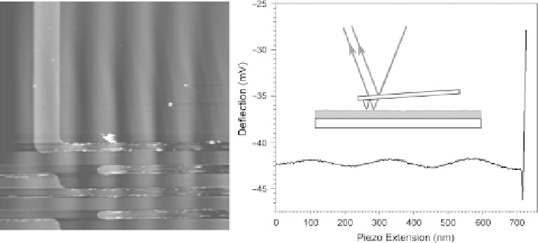
Fig. 6.20. Examples of the effect of laser interference on AFM images and force-distance curves.
Left: an image of a reflective sample, showing typical laser interference fringes. Right: the effect on
a force curve; the baseline shows similar oscillations. Inset: the artefact originates from interference
between the laser beams reflected by the cantilever and the sample.
This effect is reduced in AFM instruments with low coherence lasers, which are fitted in
newer instruments. It is also more common with patterned or reflective samples. If the user
encounters this problem, it can sometimes be reduced by adjustment of the optical
alignment of the AFM. The user should try to ensure the laser is positioned directly in
the centre of the cantilever beam, and not too close to the end. See Section 4.2.1 for a laser
spot positioning protocol.
6.6.4 Sample drift
A common problem in high-resolution microscopies is sample movement. In general,
AFM samples must be well fixed down in order to enable high-resolution imaging. At low
resolutions (scans of size larger than 5
m), some samples do not need to be fixed to the
microscope, provided they have a stable substrate. At smaller scan sizes, the sample
should be glued to a sample support, which is held (usually magnetically) in the micro-
scope. Even when firmly fixed down some samples can appear to be 'moving' in the
microscope. The reason for this is thermal expansion of the sample; this can be exacer-
bated by sources of heat in the microscope (e.g. the laser or heat from the electronics),
leading to samples moving by expansion at hundreds of nanometres per minute, which
totally precludes high-resolution imaging. Some samples (e.g. metals) are more prone than
others to this effect due to high thermal expansion coefficients.
As shown in Figure 6.21, scanning the sample with the slow scan axis in opposite
directions can help to diagnose this problem. Another major problem associated with
sample drift is that if the sample drifts in the
Z
-axis, it can prevent scanning altogether.
This can be due to expansion in the
Z
axis or expansion laterally, which effectively moves
the sample in
Z
, due to sample tilt. Although the feedback system can take account of small