Biomedical Engineering Reference
In-Depth Information
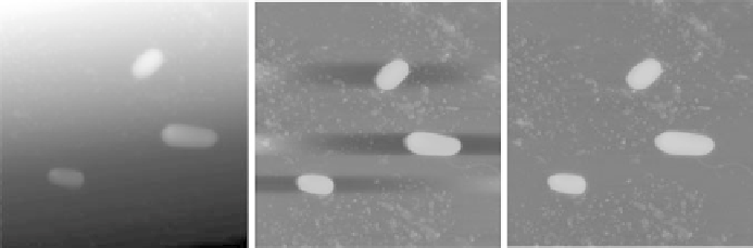
Fig. 5.3. Example showing how exclusion of features leads to improved polynomial line fitting-
based levelling. Left: raw image of bacteria, with no levelling. Middle: the same image with second
order polynomial levelling applied to the whole image - the procedure introduces artificial streaks
around the cells, and can obscure surface features. Right: the image after second order polynomial
levelling, excluding high features from the fitting - the background is completely flat.
for example in the case of particles on a flat surface, the upper 75% of the heights might be
excluded, thus only the substrate would be used for levelling.
5.1.2 Filtering
Often there is unwanted high or low-frequency noise that appears in AFM images, and this
noise may be removed by filtering. The two types of filtering most commonly used on
AFM images are matrix filtering and Fourier filtering.
Matrix filters are based on averaging adjacent points in the image, such that certain
frequency components are moved. Matrix filters are mostly grouped into so-called low-
pass and high-pass filters. Low-pass filters are so-called because they allow low-frequency
components of the image to pass, while reducing the high-frequency components. This has
a smoothing effect on the data, and so removes the high-frequency noise commonly found
in AFM images. Over-application of low-pass filters or use of large matrices will tend to
blur the data. High-pass filters, on the other hand, allow high-frequency components to
pass while reducing low-frequency components. They are usually used for sharpening or
edge detection in AFM images. Examples of low- and high-pass filters are given below:
Filter name
Equation
Remarks
2
4
3
5
3
3 mean rectangular filter
(the simplest smoothing filter).
111
111
111
4
4or5
5 matrices will
give greater smoothing
effects, and so on.
C ¼
9
2
4
3
5
3
3 simple high-pass filter
(also known as the unicrisp filter).
1
1
1
19
1
1
1
1
Larger matrices will tend to
enhance the effect of these
filters as well.
C ¼
9
Examples of the results of applying these filters to an AFM image are shown in
Figure 5.4. 5
5 matrices were applied, in order to enhance the strength of the effects
on the image.