Biomedical Engineering Reference
In-Depth Information
frequency. The automated routines cannot cope under certain conditions, so it is important
that the user knows how to manually select the frequency. This is done via a 'cantilever
tuning' window in the AFM software. This program sweeps the oscillation frequency of
the driving piezo up and down over a fixed frequency range and displays the amplitude of
oscillation at each point. The user should have some idea of the natural frequency of the
cantilever, so the start and end of the range to test in inputted to this window. This
information is supplied by the cantilever manufacturer, and typically covers quite a
broad range (e.g. 200-400 kHz). Within this range, the cantilever's oscillation should be
visible as a single, strong peak. The presence of multiple or misshapen peaks in the
frequency spectrum is an indication that something is wrong. The probe could be damaged
or not fixed correctly in the probe holder. Once the peak is located, typically the user
should zoom into the relevant part of the frequency spectrum to visualize the peak more
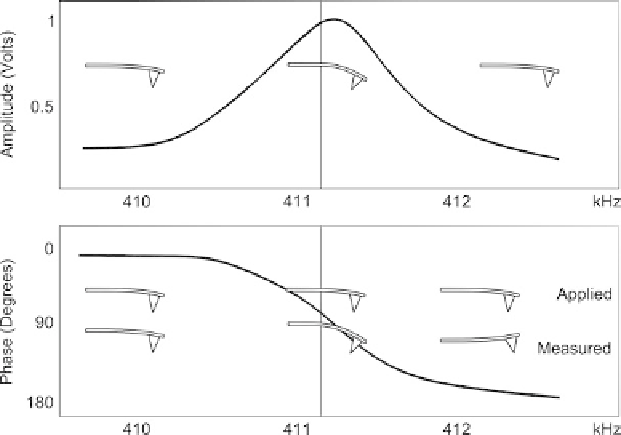
clearly. An example of the view of a cantilever tuning window is shown in Figure 4.9.
It can be seen that the instrument often shows not only oscillation amplitude versus
frequency, but also oscillation phase versus frequency. As shown here, the phase changes
180
out of phase at the amplitude maximum, the greatest slope in the phase
curve coinciding with the maximum in the amplitude curve. The meaning of these plots is
also illustrated in Figure 4.9. The resonant frequency represents the point at which the
amplitude is maximum, while the phase of the oscillation of the cantilever matches
the applied phase (
8
- being 90
8
). The actual operating frequency is at the maximum of the
amplitude, but the user usually chooses a frequency a little way off the maximum (on the
Ł ¼
0
8
Fig. 4.9. Example of real amplitude and phase versus frequency plots used in cantilever tuning. The
vertical lines represent the operating frequency, chosen by the user. Inset cartoons show the meaning
of the amplitude and phase plots. Top: the cantilever's oscillation amplitude is maximized at the
resonant frequency. Bottom: below resonant frequency, the measured cantilever oscillation follows
the applied oscillation (phase,
Ł ¼
0
8
), at resonance it lags the applied force (
Ł ¼
90
8
), and above
resonant frequency the applied oscillation lags measured oscillation further (
Ł ¼
180
8
).