Hardware Reference
In-Depth Information
Figure 6-56.
Align the expansion card with the slot and press down
firmly to seat it
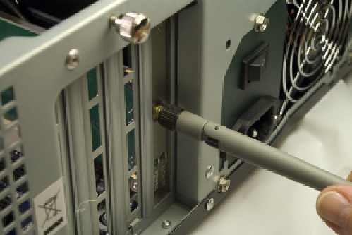
Figure 6-57.
Connect the WiFi antenna to the back of the card
FinishingUp
We're in the home stretch now. All that remains is to connect power to the case
fans and the power LED (if you choose to do that), and a few minor cleanup
tasks. Figures 6-58, 6-59, and 6-60 show Barbara connecting power for the pow-
er LED, using connector P10, and to the case fans using the P2/P3 connectors.
Figure 6-61 shows our media center system at this point in the build. Obvi-
ously, we can't leave that rats' nest of cables flopping around in there where
they might foul a fan, so the next task is to dress the cables.
Nobody's Perfect
One of our tech reviewers asked if the SATA data cables should have been routed
through the cutout between the motherboard chamber and the hard drive chamber,
and whether there was sufficient clearance for the cover with the SATA cables run
over the top edge of the bulkhead (as it isn't clear in the image). The answer to both
of those questions is yes. We should have routed the SATA cables through the cutout,
but we didn't notice that until after we'd finished building the system. And there is
sufficient clearance between the top edge of the bulkhead and the case cover, so we
elected to leave the cables as they were and simply tie them off to the chassis frame.
As Figure 6-62 shows, even at full extension the ATX12V cable wasn't long
enough to route along an edge of the motherboard, so we did the best we
could. We tried it both ways, running it along the back of the motherboard as
well as the front. We got the fan power cables secured away from the blades
and used the cable wraps to tie the cable bundles to the chassis. While we
were at it, we rerouted the SATA data cables to run them through the chassis
cutout visible underneath them in the preceding image.