Hardware Reference
In-Depth Information
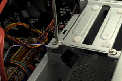
Figure 6-42.
Remove the four screws that secure the top plate of
the hard drive chamber
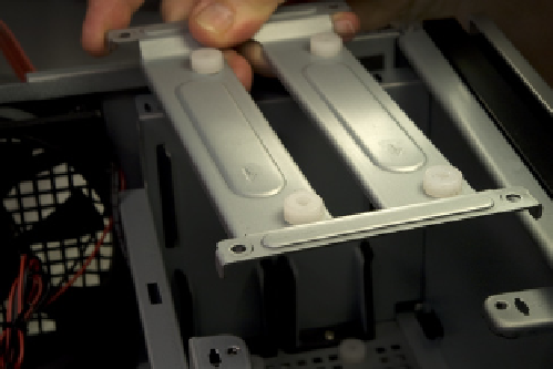
Figure 6-43.
Remove the top plate from the hard drive chamber
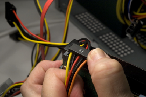
Connect an available SATA power cable to the first hard drive, as shown in
Figure 6-44. We used the P9 connector.
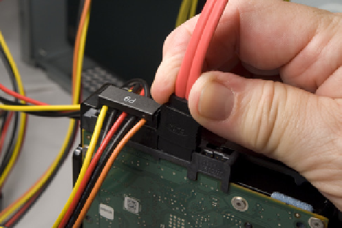
Connect a SATA data cable to the first hard drive, as shown in Figure 6-45.
Figure 6-44.
Connect a SATA power cable to the first hard drive
Figure 6-45.
Connect a SATA data cable to the first hard drive
Slide the first hard drive into the hard drive chamber, oriented as shown in
Figure 6-46.
P9 or P6?
We mentioned the connector by
number not because of function or
power provisioning, but simply to
indicate which connector we found
most convenient to use because of
cable length, connector positioning,
and so on.
Hard drives can be secured with two screws driven through the top plate and
(optionally, according to Antec) with two more screws driven through the
bottom of the case. Rather than having our hard drives hanging like bats, sus-
pended from the top plate and free-floating on the bottom, we prefer to se-
cure our drives with four screws as usual. To do that, turn the case on its side,
while supporting the hard drive to make sure it doesn't fall out. Use one hand
to wiggle the hard drive back and forth until the grommeted screw holes in
the bottom of the case align with the drive screw holes. Drive in two screws, as
shown in Figure 6-47, to secure the drive to the bottom of the case.