Hardware Reference
In-Depth Information
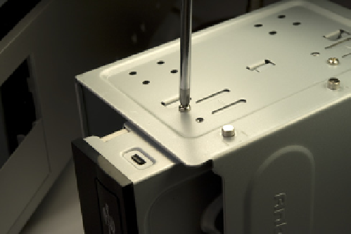
Locate the optical drive cage that you set aside earlier. Slide the optical drive
into the cage and use four or more of the provided screws to secure it, as
shown in Figure 6-34. Make sure to orient and position the optical drive as
shown. It needs to protrude from the front of the drive cage if you want the
optical drive bezel to be flush with the case bezel.
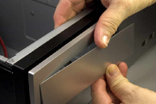
Figure 6-33.
Snap out the plastic bezel from a 5.25” external drive
bay
Figure 6-34.
Secure the optical drive to the bay with four screws
Slide the optical drive cage into the case with the front tilted downward, as
shown in Figure 6-35.
Lower the rear of the optical drive cage, making sure that the projecting nubs
on the cage frame fit into the cutouts on the chassis, and then slide the optical
drive cage into the locked position, as shown in Figure 6-36.
Figure 6-35.
Slide the optical drive cage into the case
Figure 6-36.
Slide the optical drive cage into the chassis
Locate an available SATA power cable from the power supply and connect it to
the optical drive power connector, as shown in Figure 6-37. (We used the SATA
power cable with the P5 connector.) Make sure the L-shaped keys on the cable
connector and drive connector are aligned properly, and then press the cable
connector onto the drive connector until it seats completely.