Hardware Reference
In-Depth Information
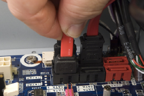
Figure 6-26.
Connect the SATA data cables to the motherboard
ports
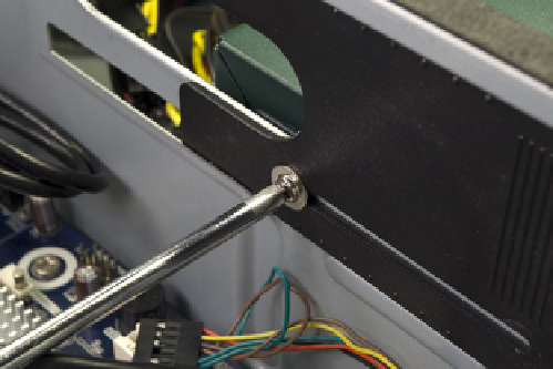
Figure 6-27.
Loosen the screw that secures the access panel
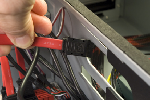
Pass the free end of the optical drive SATA data cable through the access door
and into the chamber that contains the optical drive bay, as shown in Figure
6-28.
Figure 6-28.
Pass the SATA data cable for the optical drive into the power supply chamber
Routingandconnectingpowertothemotherboard
The next step is to route the main ATX power cable and the ATX12V (CPU)
power cable from the power supply chamber to the motherboard chamber
and connect those cables. To begin, pass the 24-pin main ATX power cable
from the power supply chamber into the motherboard chamber, as shown in
Figure 6-29.
Align the 24-pin main ATX power cable connector with the motherboard sock-
et, as shown in Figure 6-30, and press down firmly until it snaps into place.
Examine the connection visually to verify that the connectors are fully mated
and that the latch has engaged. A partially seated main ATX power connector
can cause subtle problems that are very difficult to troubleshoot.