Hardware Reference
In-Depth Information
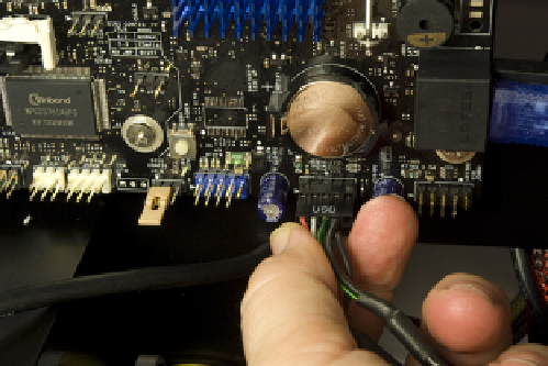
Locate the dual-port USB 2.0 cable in the bundle of front-panel cables coming
from the top front of the DF-85 case. Route that cable to one of the USB 2.0
header-pin sets on the motherboard. Orient the cable connector so that the
blocked hole in the connector corresponds to the missing pin in the mother-
board header-pin set. Press the cable connector onto the header pins until it
seats completely, as shown in Figure 5-48.
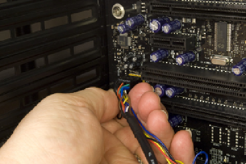
Figure 5-47.
Connect the front-panel HD audio cable to the
motherboard
Figure 5-48.
Attach the front-panel dual-port USB 2.0 cable to a
motherboard USB 2.0 header-pin set
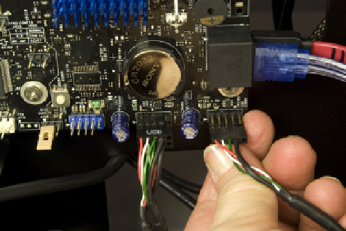
Locate the single-port USB 2.0 cable in the bundle of front-panel cables. Route
that cable to a second motherboard USB 2.0 header-pin set. Orient the cable
connector so that the blocked hole in the connector corresponds to the miss-
ing pin in the motherboard header-pin set. Press the cable connector onto the
header pins until it seats completely, as shown in Figure 5-49.
The next step is to connect the power switch, reset switch, and hard drive ac-
tivity LED, as shown in Figure 5-50. The two switches are not polarized and
may be connected in either orientation. The HDD LED cable connector is po-
larized, with the black wire as ground and the red wire as positive. Orient the
cable connector with the red wire corresponding to the HDD+ pin.
Figure 5-49.
Attach the front-panel single-port USB 2.0 cable to a
motherboard USB 2.0 header-pin set
Figure 5-50.
Connect the power switch, reset switch, and HDD
LED cables