Hardware Reference
In-Depth Information
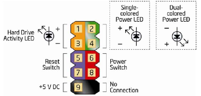
Figure 4-44.
Intel DH55TC front-panel switch and indicator pinouts (image courtesy of
Intel Corporation)
We'll connect three of those cables to the monolithic connector block mapped
in Figure 4-44. The one exception is the power LED, because Intel provides two
adjacent pins for that connection, while the Antec Mini P180 case provides
a three-position/two-pin power LED cable that does not fit this block. Fortu-
nately, the Intel DH55TC motherboard provides an alternative three-position/
two-pin motherboard connector that the Antec cable fits. That connection is
shown at the bottom center of Figure 4-45 as a blue/white cable connected
to the pin set labeled PWR LED. Connect the power switch cable and reset
switch cable to the monolithic connector block, as shown in Figure 4-45. Polar-
ity doesn't matter for switches, so you can install the cable connector in either
direction. Connect the HDD LED cable to the appropriate pins, making sure
to observe polarity. (The red wire is positive and the white wire is ground.) If
you connect this cable backward, no harm is done, but the HDD LED won't
function.
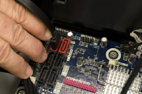
Locate the black front-panel eSATA cable, and connect it to one of the red eSATA
motherboard ports as shown in Figure 4-46. It doesn't matter which one. Make
sure the L-shaped key in the cable connector and motherboard connector
mate, and then press the cable connector down firmly until it seats.
Figure 4-45.
Connect the front-panel switch and indicator cables
Figure 4-46.
Connect the front-panel eSATA cable