Hardware Reference
In-Depth Information
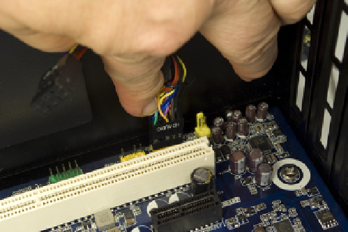
the front-panel HD audio header-pin set, toward the rear corner of the mother-
board, near the expansion slots. The header-pin set is keyed with a missing pin
that corresponds to a blocked hole on the cable connector. Orient the cable
connector and header pins so that the keying matches, and then press the
cable connector onto the header pins, as shown in Figure 4-42.
eUSB?
Embedded USB SSDs are not used
in general-purpose PCs. They were
designed to replace 1.8” hard drives
in embedded, ruggedized, and mil-
spec systems, where they serve as the
only mass storage device. eUSB SSDs
generally use expensive SLC memory
and have capacities in the 500 MB to
16 GB range. A 1 GB eUSB SSD may
cost $35, a 4 GB model $125, and a
16 GB model $500.
In addition to six rear-panel USB ports, the Intel DH55TC motherboard in-
cludes three sets of header pins that each provide two USB ports, for a total of
12 USB ports. The center USB header-pin set also includes special support for
an internal
embedded USB
(eUSB) solid-state drive.
We don't expect to install an SSD in this system, and if we did it would be
one that uses a standard SATA interface. Even so, with more USB ports on the
motherboard than we have places to connect them, we decided to use one of
the remaining two USB header-pin sets. One of those sets is located near the
front corner of the motherboard, in close proximity to the front-panel switch
and indicator pins. To make it easier to install the latter, we decided to use the
second USB header-pin set, located just to the rear of that first set.
Like the front-panel audio connectors, the USB cable connector and header-
pin set are keyed with a blocked hole and missing pin, respectively. (The USB
key pin is different from the audio key pin, to make sure you can't accidentally
connect a USB port to the audio header pins, or vice versa.)
To make the connection, orient the front-panel USB cable plug to align its
blocked hole with the missing pin on the USB header-pin set. Slide the cable
connector down onto the header pins, as shown in Figure 4-43, until it seats
completely.
Figure 4-42.
Connect the front-panel audio cable HD audio con-
nector to the FP audio header-pin set
Figure 4-43.
Connect the front-panel USB cable connector to the
USB header-pin set
Next up are the front-panel switch and indicator cables: namely, the power
and reset switches, the hard drive activity LED, and the power LED. Figure
4-44 shows the pinouts for these switches and indicators on the Intel DH55TC
motherboard. (Actually, this is an Intel standard, used by all recent Intel mother-
boards and most motherboards from other makers.)