Hardware Reference
In-Depth Information
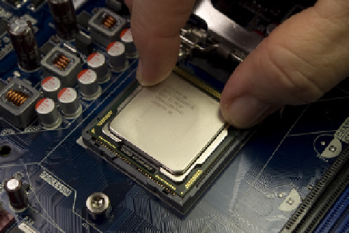
Figure 4-22.
Align the processor with the socket and then drop the
processor into the socket
Figure 4-23.
Lower the load plate into the closed position
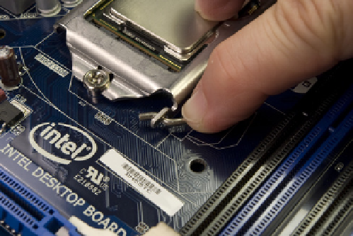
Figure 4-24.
Lower the processor lever to cam the load plate into
locked position
Figure 4-25.
Close the processor lever completely and snap it into
the latch on the load plate
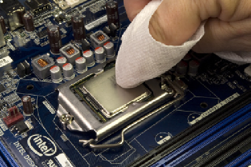
Figure 4-26.
If necessary, polish the surface of the processor with
a clean paper towel
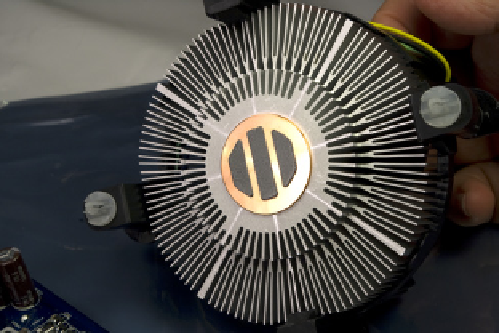
Figure 4-27.
Verify that the thermal compound is present and
undamaged on the base of the heatsink