Hardware Reference
In-Depth Information
Connectingfront-panelswitchandindicatorcables
The next step is to connect the front-panel switch and indicator cables to the
motherboard. Before you begin connecting front-panel cables, examine the
cables. Each is labeled to indicate its purpose. Match those labels with the front-
panel connector pins on the motherboard to make sure you connect the correct
cable to the appropriate pins. Once you determine the proper orientation for
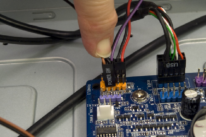
each cable, connect it as shown in Figure 3-35.
Figure 3-35.
Connect the front-panel switch and indicator cables
Keep the following guidelines in mind as you connect the front-panel cables:
• Although Intel has defined a standard front-panel connector block and uses
that standard for its own motherboards, few other motherboard makers ad-
here to that standard. Accordingly, rather than providing an Intel-standard
monolithic connector block that would be useless for motherboards that
do not follow the Intel standard, most case makers, including Antec, pro-
vide individual one-, two-, or three-pin connectors for each switch and
indicator.
• Not all cases have cables for every connector on the motherboard, and
not all motherboards have connectors for all cables provided by the case.
• The power switch and reset switch connectors are not polarized and can
be connected in either orientation.
• LED connectors are polarized and should be connected with the ground
wire and the signal wire oriented correctly. Most cases use a common wire
color—usually black, although sometimes white or green—for ground,
and a colored wire for signal.
• The power LED connector is often problematic, as it is for this system.
There are two types of power LED connector. The first has two pins. The
second has three pins, but only two wires, with the middle pin unused.