Hardware Reference
In-Depth Information
If the metal contacts on the base of the module are not visible and the DIMM
otherwise appears to be fully seated, simply use finger pressure to snap the
latching tabs into position.
Figure 3-23.
Open the DIMM locking tabs on both sides of both
memory sockets
Figure 3-24.
Align the memory module with the socket
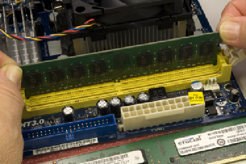
Figure 3-25.
Press straight down on both sides of the memory
module until it seats completely in the socket
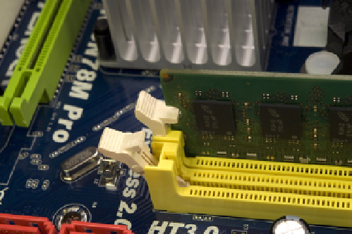
Figure 3-26.
Verify that the memory module is latched into position
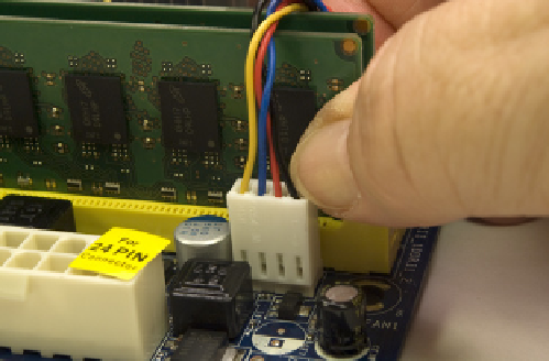
With the memory installed, you can now connect
power to the CPU fan. This connector is keyed by plas-
tic tabs on the cable connector and the motherboard
header-pin set to prevent it from being connected in-
correctly. Align the cable connector with the header
pins and press the cable connector onto the header
pins, as shown in Figure 3-27.
The motherboard is now prepared. Place it aside for
now. Use the antistatic foam under the motherboard
to make sure it's not damaged by static electricity.
Figure 3-27.
Connect the CPU fan power cable to the CPU fan
header pins