Graphics Reference
In-Depth Information
Computing
environment
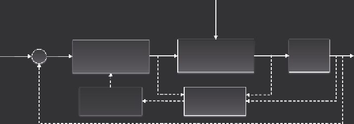
Performance
objective,
r
Error,
e
Disturbance,
d
Output,
y
u
Plant
(Rendering Process)
QoS
Evaluator
Controller
C
Controller
Designer
Model Estimator
M
FIGURE 5.3
(See colour insert.)
Rendering system with adaptive controller and quality of
service feedback.
is introduced as an additional evaluation step to compute qualitative performance in
addition to evaluating plant output only.
Furthermore, a model estimator (Figure 5.3) may be used to provide periodic
assessments of plant dynamics so that an appropriate control strategy can be com-
puted and implemented to meet performance requirements. This approximation of
the plant model forms an important basis to allow a designer to make decisions about
changing control parameters or introducing new control laws into a control system.
Astrom and Wittenmark's research on adaptive control [53] provides insight into
controller design based on a plant with uncertain parameters and dynamics.
The advantage of the control system described in Figure 5.3 lies in the flexibility
of controller design that is not fixed and whose parameters do not need to be known
at design time. While elaborate control system designs may be considered plausible
solutions to the frame rate inconsistency problem in computer graphics rendering,
they may not always be computationally effective for use in real-time applications
due to their complexity.
An intuitive step to circumvent this problem is to design a control system in
a modularised manner and treat the plant and control as separate subsystems.
This architecture provides greater flexibility for the controller and plant because
computing resources are dedicated to each subsystem and any disturbance arising
from controller-related computation would not affect plant operation. The feedback
data channel and feed-through from the controller to the plant can be achieved by
network communication. The design of this modular control system is presented
in Figure 5.4.
An additional consideration for the design shown in Figure 5.4 is the data trans-
port overhead arising from the inter-subsystem communication. In typical control
engineering applications, this can be modelled analogously as delays from actuators
and sensors. These delay components are illustrated as components of the commu-
nication channels in Figure 5.4.
In summary, we have provided a systematic and progressive introduction of the control
system perspective for the real-time rendering. We also presented a high level overview
of the various control system architectures and relevant implementation considerations.
Search WWH ::

Custom Search